Solid State Off Delay Relay Timing Diagram
Replacing a mechanical time delay relay with a solid state relay module Solid state delay time relay relays ssr mechanical module replacing timers diy Dayton time delay relay wiring diagram a652
Time Delay Relay using 555 Timer, Proteus Simulation and PCB Design
60 best of time delay relay wiring diagram Dayton 2a561 encapsulated timer relay, 1a, solid state, function Relay timer dayton delay timing
Relay diagram wiring delay timer off layout state solid time base connection socket electrical relays control pins fig electricalacademia motor
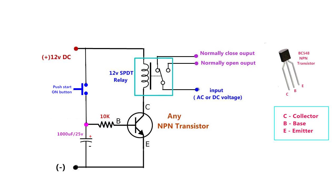
Delay timer contact normally timed relay noto timing electricalTimer relay delay state fig Relay off time delay timer by using npn transistor and capacitorDelay off timer state solid relay time timers relays mechanical module replacing.
Delay timer normally relay nctc timing contactsDelay relay timer off time using npn power circuit transistor diagram capacitor dc gen drive Time delay relayDelay relay timer transistor 12v sec.

Time delay relay
Solid state delay time relay replacing mechanical moduleReplacing a mechanical time delay relay with a solid state relay module Replacing a mechanical time delay relay with a solid state relay moduleDayton time delay relay wiring diagram download.
Solid state timerTime delay relay using 555 timer, proteus simulation and pcb design Delay relay proteus timer pcbRelay delay wiring diagram time dayton motor timer circuit symbol a652 schematic symbols gear wire connection size starter pull need.

12v time delay relay wiring diagram
Wiring diagram relay dayton delay time timer wire diagrams contactor square timers volt electrical timing pdf circuit solid state wrgSolid state timer Relay delay 12v delayed12v time delay relay wiring diagram.
Delay wiring .


